Abstract A systematic and detailed description of the application of screen printing in the preparation of microelectrodes was made, and the procedures for the printing of the stretch net, the positive base plate, the photosensitive emulsion, the drying net, the development, the hard mask, and the printing were described. The necessary precautions and tips were summarized. The effects of the marking method, exposure time, and development time were examined, and microelectrodes were fabricated under optimized conditions. Cyclic voltammetry scans were performed on a microelectrode using 1 mmol/L potassium ferricyanide. The results show that the obtained microelectrode strip has good electrochemical performance. With this method, inexpensive microelectrode strips suitable for electrochemical research and application can be produced in large quantities.
Key words screen printing, microelectrodes, electrochemistry
1 Introduction
Screen printing originated in China and has a history of two thousand years. Since the 1970s, with the development of science and technology, the application of screen printing has become increasingly widespread, and has gradually penetrated into the field of analytical chemistry, and has become an important method for preparing thin-film microelectrodes.
The basic principle of screen printing [1] is that part of the mesh of the screen printing plate can penetrate the ink and print on the printing material; while the rest of the mesh is blocked and can not pass through the ink, forming on the printing material. blank. Modern general photochemical platemaking method, the law is to tighten the screen on the screen frame, and then coated with sensitized film on the Internet to form a photosensitive film, and then close the positive plate on the plate in the print version, after exposure, Developing, the part of the printing plate that does not need to pass the ink receives the light to form the cured edition film, seals the mesh hole, does not penetrate the ink when printing; The part of the mesh that needs to pass the ink on the printing plate is not closed, the printing ink passes, Ink forms on the substrate.
Due to the simple equipment and low investment required for screen printing technology, the advantages of inexpensive disposable electrodes can be prepared. There are many related researches at home and abroad [2~4], but most of the literature on printed electrode technology itself involves very little [5, 6]. The existing screen printing books and materials only focus on screen printing in textile printing and dyeing. For applications such as advertising and production, there are no reports of printed microelectrode in the literature so far. Based on experimental results, this study reported on the application of screen printing technology in microelectrode preparation.
2 experimental part
2.1 Instrument and Reagent
Aluminium alloy frame (400 mm × 300 mm); stretcher; adhesive mesh; wire mesh (40μm, imported polyester, specifications: VS2MonOPR INT, PES. 140 / 35 PW, Made in Germany; print box (homemade) CH I900 Scanning Electrochemical Microscope (CH I, USA).Photosensitive Adhesive (China Institute of Printing Science and Technology); conductive silver paste (GA21038); conductive carbon ink (Electrodag 423 ss, Acheson colloids company); Ag/AgCl paste ( C610037P7, Gwent Electronic Materials L td. ); Methylene Blue (China Pharmaceutical Group, Shanghai Chemical Reagent Company); NaCl, KCl are all analytically pure;
2. 2 electrode printing
2. 2. 1 Stretching the net The aluminum alloy frame to be stretched is placed horizontally on the ground and the stretcher is clamped. The top surface of the net frame is coated with a sticky net adhesive. After 3 to 5 minutes, the latitude and longitude direction of the screen is bonded to the net frame in parallel, and the screen is then stretched with a stretcher to wait for about 1 hour. The sticky mesh can be removed after being dried thoroughly, and placed in a ventilated place for 1 d before use.
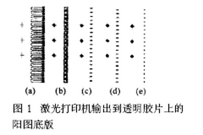
2. 2. 2 Method for making positive panels The bottom method for positive panels includes the drawing method, the cutting film method, and the photoengraving method. The drawing method and the cutting film method belong to the manual plate making method, and the photoengraving method is the main method for modern silk printing plates. . The original plate made in this experiment is a monochrome line, so the computer graphics are used, and the laser printer outputs the transparent picture film to make the positive figure bottom plate. Modern ordinary laser printers can print at a resolution of 720 dp i (smaller than the eye's resolution), making it possible to produce a very small positive panel for electrodes, as shown in Figure 1.
2. 2. 3 Coat the sensitized adhesive in the darkroom to prepare sensitized glue, stir well, and wait until the foaming is complete. With a clean brush dipped in an aqueous solution of detergent, the two sides of the screen are brushed clean, the tap water rushes to no bubble, the cold air is blown dry, and the photosensitive adhesive is coated with a glue applicator in the dark room. Leaning the frame against the wall, with the mesh facing outwards, hold the two ends of the applicator in one hand and apply the coating from top to bottom. The glue will slowly flow downwards under the action of gravity. The mesh frame is inverted upside down, so that the glue is evenly distributed, and the mesh surface is placed flat on the oven frame and the cold air is blown dry.
2. 2. 4 Take a piece of plexiglass plate that is similar in thickness to the mesh frame and slightly smaller than the inner edge of the frame. After washing and drying, place the positive side of the printed image on the printed side of the positive side to be printed with the transparent adhesive cloth. Posted well. NOTE To completely overlap the pattern, place the plexiglass plate with the layout facing up in the center of the glass on the blueprint box. In the dark room, put the coated plastic frame of the photoresist on the top of the plexiglass plate, add a leveling weight to make the adhesive surface and the positive bottom plate film closely, and then cover the printing plate with a black cloth. Prevent the penetration of ultraviolet rays. After 5 minutes of powering, remove the sturdy frame and develop it.
2. 2. 5 Development In the dark room, immerse the exposed net frame in clean water and remove it after 5 h.
2. 2. 6 The firm membrane will wash the net frame after development from the inside with tap water, place it in the oven in the cold wind and dry it, and then put it on the exposure box to expose the two sides respectively for about 15 min.
2. 2. 7 Printing Printing can be carried out in several steps depending on the complexity of the electrode being printed. Taking the simplest three electrodes printed as an example, step-by-step printing of conductive silver paste, insulating layer, carbon counter electrode layer, carbon working electrode layer, and silver/silver chloride reference electrode layer (a respectively FIG. 1 a, FIG. b, c, d, e patterns). After each step is printed, it should be placed in an oven and dried for more than 12 hours before proceeding to the next step.
After all the printing is completed, it is dried in an oven for 24 hours, and the electrodes can be used after being cut.
2. 3 Inspection
The printed electrodes were ultrasonically washed with acid and alkali and then subjected to cyclic voltammetry with 1 mmol/L potassium ferricyanide solution (0.1 mol/L HCl, 0.1 mol/L KCl).
3 Results and Discussion
3.1 Influence of Stretching Net on Printed Graphics
The key to stretching the net is that the latitude and longitude lines of the screen should be kept parallel to the sides of the frame in order to print the electrode strips with smooth edges. Otherwise, printed electrodes may appear jagged and affect the conductivity of the electrodes.
3.2 The choice of positivity software and the design of alignment marks
There are many kinds of computer graphics software, such as Windows drawing tools, Cool Draw, Photoshop, Protel, etc. They can all be used for drawing, but comparatively, Photoshop with its powerful graphics processing capabilities and precise fine positioning capabilities and image The fidelity output function is most suitable for the positive plate of the prepared microelectrode.
The electrode material used for the electrochemical measurement of the micro thin film three electrodes is generally different. A carbon film is used as a counter electrode, and an Ag/AgCl film is used as a reference electrode. If the working electrode is a carbon electrode, at least three kinds of materials are required. Web printing can only print one material at a time, and multiple materials require printing multiple times. Multiple prints require careful consideration of alignment marks during drawing. In the actual printing process, the advantages and disadvantages of various alignment mark methods were compared. The results are shown in Table 1.
Printed film will have a small amount of missing ink or residual ink in the subtle part. This is due to the fact that the printer prints thinner lines and larger pieces of electrode parts and cannot completely eliminate them. Therefore, the printed film is subjected to further manual processing, removing the excess portion, and the missing portion is traced with an oil-based pen. In order to deepen the blackness of the ink, two to three sheets of the same film are stacked together as the positive image substrate. This can achieve very good practical results.
Bady/Adult Diaper Raw Materials
Bady/Adult Diaper Raw Materials,Adult Diapers,Adult Diaper Rash,Adult Diapers Amazon
Bady/Adult Diaper Raw Materials Co., Ltd. , http://www.nbbadydiaper.com